|
|
|
|
How Fiber Optics Work |
||||||||||
|
You hear about fiber-optic cables whenever
people talk about the telephone
system, the cable TV
system or the Internet.
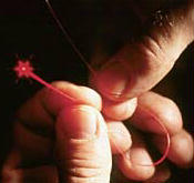
Fiber-optic lines are strands of optically pure glass as thin as a
human hair that carry digital information over long distances. They are also
used in medical imaging and mechanical engineering inspection. In this edition of HowStuffWorks, we
will show you how these tiny strands of glass transmit light and the
fascinating way that these strands are made. What are Fiber Optics?
If you look closely at a single optical
fiber, you will see that it has the following parts:
Hundreds or thousands of
these optical fibers are arranged in bundles in optical cables. The bundles
are protected by the cable's outer covering, called a jacket. Optical fibers come in two types:
Single-mode fibers have small cores (about 3.5 x 10⁻⁴ inches or 9 microns in diameter) and transmit
infrared laser light
(wavelength = 1,300 to 1,550 nanometers). Multi-mode fibers have
larger cores (about 2.5 x 10⁻³ inches or
62.5 microns in diameter) and transmit infrared light (wavelength = 850 to
1,300 nm) from light-emitting
diodes (LEDs). Some optical fibers can be made from plastic.
These fibers have a large core (0.04 inches or 1 mm diameter) and transmit
visible red light (wavelength = 650 nm) from LEDs. Let's look at how an optical fiber works. How Does an Optical Fiber
Transmit Light?
The light in a fiber-optic cable travels
through the core (hallway) by constantly bouncing from the cladding (mirror-lined
walls), a principle called total internal reflection. Because the
cladding does not absorb any light from the core, the light wave can travel
great distances. However, some of the light signal degrades within the
fiber, mostly due to impurities in the glass. The extent that the signal
degrades depends on the purity of the glass and the wavelength of the
transmitted light (for example, 850 nm = 60 to 75 percent/km; 1,300 nm = 50
to 60 percent/km; 1,550 nm is greater than 50 percent/km). Some premium
optical fibers show much less signal degradation -- less than 10 percent/km
at 1,550 nm. A Fiber-Optic Relay System Now, imagine doing this when the ships are
on either side of the ocean separated by thousands of miles and you have a
fiber-optic communication system in place between the two ships. Fiber-optic
relay systems consist of the following:
Transmitter The transmitter is physically close to the
optical fiber and may even have a lens to focus the light into the fiber.
Lasers have more power than LEDs, but vary more with changes in temperature
and are more expensive. The most common wavelengths of light signals are 850
nm, 1,300 nm, and 1,550 nm (infrared, non-visible portions of the spectrum). Optical
Regenerator An optical regenerator consists of optical
fibers with a special coating (doping). The doped portion is "pumped" with a laser. When the degraded
signal comes into the doped coating, the energy from the laser allows the
doped molecules to become lasers themselves. The doped molecules then emit a
new, stronger light signal with the same characteristics as the incoming weak
light signal. Basically, the regenerator is a laser amplifier for the
incoming signal (see this
page on fiber amplifiers for more details). Optical
Receiver For a good discussion of lightwave
transmission systems, see this
page from Bell Labs. Advantages of Fiber Optics
Because of these
advantages, you see fiber optics in many industries, most notably
telecommunications and computer networks. For example, if you telephone
Europe from the United States (or vice versa) and the signal is bounced off a
communications satellite,
you often hear an echo on the line. But with transatlantic fiber-optic
cables, you have a direct connection with no echoes. How Are Optical Fibers
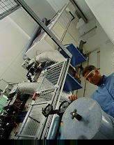
Made? Making optical fibers requires the
following steps:
Making the
Preform Blank
In MCVD, oxygen is bubbled through
solutions of silicon chloride (SiCl4), germanium
chloride (GeCl4) and/or other chemicals. The precise mixture
governs the various physical and optical properties (index of refraction,
coefficient of expansion, melting point, etc.). The gas vapors are then
conducted to the inside of a synthetic silica or quartz tube
(cladding) in a special lathe. As the lathe turns, a torch is moved up
and down the outside of the tube. The extreme heat from the torch causes two
things to happen:
The lathe turns continuously to make an
even coating and consistent blank. The purity of the glass is maintained by
using corrosion-resistant plastic in the gas delivery system (valve blocks,
pipes, seals) and by precisely controlling the flow and composition of the
mixture. The process of making the preform blank is highly automated and
takes several hours. After the preform blank cools, it is tested for quality
control (index of
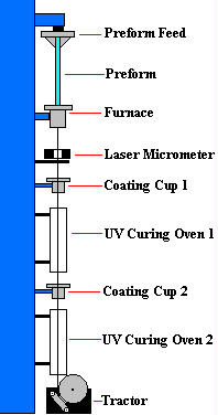
refraction). Drawing Fibers
from the Preform Blank
The blank gets lowered into a graphite
furnace (3,452 to 3,992 degrees Fahrenheit or 1,900 to 2,200 degrees Celsius)
and the tip gets melted until a molten glob falls down by gravity. As it drops,
it cools and forms a thread.
The operator threads the strand through a series
of coating cups (buffer coatings) and ultraviolet light curing ovens onto a
tractor-controlled spool. The tractor mechanism slowly pulls the fiber from
the heated preform blank and is precisely controlled by using a laser
micrometer to measure the diameter of the fiber and feed the information
back to the tractor mechanism. Fibers are pulled from the blank at a rate of
33 to 66 ft/s (10 to 20 m/s) and the finished product is wound onto the
spool. It is not uncommon for spools to contain more than 1.4 miles (2.2 km)
of optical fiber. Testing the
Finished Optical Fiber
The finished optical fiber is tested for
the following:
Once the fibers have
passed the quality control, they are sold to telephone companies, cable
companies and network providers. Many companies are currently replacing their
old copper-wire-based systems with new fiber-optic-based systems to improve
speed, capacity and clarity. Physics of Total Internal
Reflection At one particular angle (critical angle),
the refracted light will not go into m2, but
instead will travel along the surface between the two media (sin [critical
angle] = n2/n1 where n1 and n2 are the
indices of refraction [n1 is less than n2]). If the beam through m1 is greater than the critical angle, then the
refracted beam will be reflected entirely back into m1 (total internal reflection), even though m2 may be transparent! In physics, the critical angle is
described with respect to the normal line. In fiber optics, the critical
angle is described with respect to the parallel axis running down the middle
of the fiber. Therefore, the fiber-optic critical angle = (90 degrees -
physics critical angle).
In an optical fiber, the light travels
through the core (m1, high index of
refraction) by constantly reflecting from the cladding (m2, lower index of refraction) because the angle of
the light is always greater than the critical angle. Light reflects from the
cladding no matter what angle the fiber itself gets bent at, even if it's a
full circle! Because the cladding does not absorb any
light from the core, the light wave can travel great distances. However, some
of the light signal degrades within the fiber, mostly due to impurities in
the glass. The extent that the signal degrades depends upon the purity of the
glass and the wavelength of the transmitted light (for example, 850 nm = 60
to 75 percent/km; 1,300 nm = 50 to 60 percent/km; 1,550 nm is greater than 50
percent/km). Some premium optical fibers show much less signal degradation --
less than 10 percent/km at 1,550 nm. |
Note: This
document is from howstuffworks site. Here it is used for educational purpose.
All rights are reserved with related sites.